
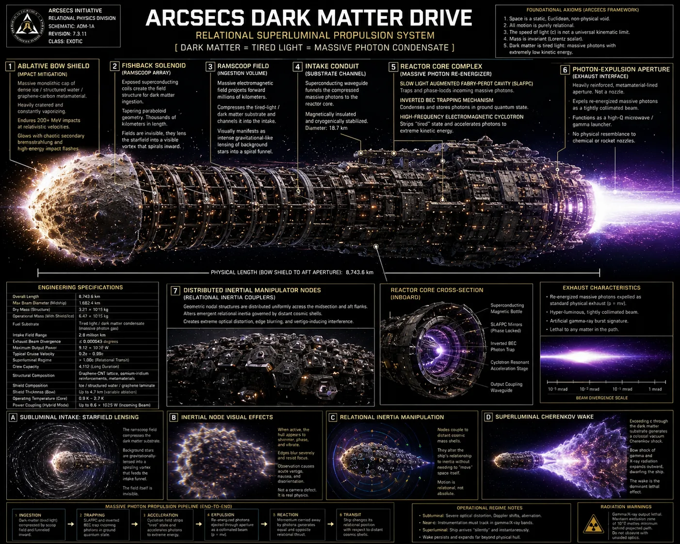
DarkMatterDrive.com — ArcSecs Relational Propulsion Atlas DarkMatterDrive.com — ArcSecs Relational Propulsion Atlas

Trans-cosmic flight logic

Navigation by relational mass geometry

The drive crosses the cosmic bubble by exploiting changing relationships to galactic mass distributions: departure inertia decay, centerline equilibrium, distal gravitational induction, distorted star fields, autonomous timing references, and radiation-heavy optical hazard filtering.

Navigation by relational mass geometry - Dark Matter Drive schematic

Direct answer

What this page is arguing

Dark Matter Drive navigation is not “point at a star and fly fast.” It is a speculative guidance stack that treats position, inertia, hazard detection, and thrust balance as relational measurements.

Navigation in the Dark Matter Drive framework means measuring relationships to mass distributions, light fields, clock references, and sensor beacons while the craft’s own propulsion distorts what it sees. The ship cannot rely on a simple visual star map, because extreme acceleration, blueshift, radiation, field effects, and time-of-flight delays all corrupt normal intuition.

This page expands the argument while keeping the trust boundary visible: real navigation uses ephemerides, tracking, astrometry, standards, and sensor fusion; the Dark Matter Drive-specific “relational mass geometry” layer remains a site hypothesis and a site-authored conceptual model.

Three regimes

The cosmic bubble transit

The journey is divided into three relational kinetic phases. Each phase has a different navigation problem, not merely a different speed.

Phase 1

Departure and local inertia decay

As the vessel leaves dense local mass concentrations, its relational inertial resistance falls and the same thrust yields rising acceleration. Navigation emphasis: keep attitude stable, map nearby hazards, compare expected acceleration to observed acceleration, and avoid overcorrecting while the coupling environment changes.

Phase 2

Center equilibrium

At the cosmic centerline, distant mass is modeled as more symmetrically distributed. Fuel density is maximized and the ship crosses in a stabilized high-thrust regime. Navigation emphasis: maintain corridor lock, preserve reference-frame confidence, and prevent sensor saturation from turning a straight path into an unobservable path.

Phase 3

Distal pull and braking profile

After the center, the far side of the bubble dominates. The drive uses gravitational induction as a towline while modulating exhaust to avoid catastrophic arrival. Navigation emphasis: convert route geometry into a braking schedule, resolve destination motion, and keep the arrival cone survivable.

Precision stack

How sensors survive impossible optics

The ship cannot navigate by normal star maps. It needs extreme metrology and autonomous interpretation of distorted, blueshifted, and radiation-heavy signals.

Avionics

SAGITTA star trackers

Primary relational navigation by distorted stellar profiles and sub-arcsecond vector alignment. The tracker does not just ask “where is the star?” It asks which shifted pattern best matches a known source under the current field model.

Avionics

TWINKLE distributed trackers

Miniaturized redundant hull constellation for secondary verification and distributed attitude data. If the bow is blinded, the hull constellation can still recover orientation from side and aft references.

Avionics

SCORPIO radiation-hardened trackers

Deep-space resilience against high-energy Proca-field and exhaust environment contamination. These trackers are the last resort when ordinary optical channels are saturated.

Stability

ZYRA reaction wheels

Low-microvibration attitude control to prevent condensate decoherence and SLAFPC resonance loss. A navigation command that destroys field stability is not a successful correction.

Computation

Arcsec Digital AI

Real-time Weber-force vector calculation, catalog matching, hazard ranking, and telemetry fusion for relational thrust balancing.

Crew safety

Optical hazard filtering

Multispectral sensor fusion replaces human-visible navigation when forward light shifts into ultraviolet, X-ray, and gamma bands.

Route solving

From destination to survivable corridor

A destination is not enough. The system needs a safe corridor, a thrust law, a braking profile, and a confidence score.

1. Destination state

Resolve the destination’s predicted position, velocity, and uncertainty at arrival time, not at departure time. A high-speed route must aim at where the destination system will be, not where its old light says it was.

2. Corridor selection

Select a corridor that minimizes hazard exposure and sensor blindness. The best route may avoid dense dust bands, strong radiation fields, or geometric zones where reference sources collapse into an ambiguous forward cone.

3. Inertial-gradient forecast

Estimate where the craft’s acceleration response changes as distant mass relationships change. In the site model, this forecast is essential for avoiding runaway acceleration or insufficient braking authority.

4. Continuous route audit

Compare predicted observations to actual observations. If stars, pulsar-like timing sources, radiation signatures, or inertial response disagree, the system lowers confidence and requests a route correction.

5. Braking schedule

Arrival is the most dangerous maneuver. Braking must begin before ordinary visual confirmation feels intuitive because light-delay, apparent-position errors, and structural limits make “wait until you see it” catastrophic.

6. Abort geometry

A serious navigation model needs failure exits: a safe coast mode, a non-destructive thrust cutoff, field-stability recovery, and a way to stop chasing a false target.

Failure modes

What can go wrong

These failure modes turn the page from pure lore into an engineering-style checklist.

Failure mode

Star-field aliasing

Distorted light makes the observed sky match the wrong catalog solution. The ship thinks it knows its attitude, but it has locked onto a false pattern.

Failure mode

Inertial overshoot

The route model underestimates a drop in inertial resistance and the same thrust produces too much acceleration.

Failure mode

Sensor saturation

Forward light and radiation saturate the primary optical channel, forcing a shift to side, aft, radio, timing, or radiation-hardened references.

Failure mode

Destination light-delay trap

The craft navigates toward stale target information rather than the destination state at arrival time.

Failure mode

Hazard cone compression

Dust, debris, or radiation hazards compress into a forward cone faster than the system can classify them.

Failure mode

False braking confidence

The ship begins braking on an inaccurate inertial-gradient forecast and arrives too fast or too far off-axis.

Trust boundary

What is real background and what is project hypothesis

This page deliberately separates real navigation disciplines from Dark Matter Drive-specific speculation.

Established background

Ephemerides, astrometry, deep-space tracking, timing standards, catalog matching, sensor fusion, and autonomous navigation are real engineering/science topics.

Site hypothesis

Relational mass geometry, cosmic bubble transit, inertia decay profiles, and distal gravitational induction are Dark Matter Drive project language and should be treated as speculative unless separately validated.

Visual simulation

The page’s route diagrams, star-field distortions, and sensor-stack descriptions are explanatory models. They can make a concept inspectable, but they do not prove the drive works.

Needs validation

Any claim that the craft can exploit distant mass shells for navigation or braking requires equations, predictions, independent critique, and comparison with observations.